email sig
- Published: Tuesday, 08 May 2018 17:05
- Written by Super User
- Hits: 2610

- Category: Uncategorised
Induction Information
- Published: Tuesday, 22 November 2016 12:48
- Written by Super User
- Hits: 5656
Contractor Responsibilities
Contractors must:
- Notify their supervisor and the relevant J&T Mechanical Installation contact in writing when undergoing medical treatment, taking prescribed medication or 'over-the- counter medication', in any circumstance where such occurrences have the potential to affect safety in the workplace. In circumstances where their treating medical practitioner does not consider safety to be affected, they must provide a certificate to their supervisor and Company contact verifying this advice
- Fully cooperate with J&T Mechanical Installation in relation to the application of this procedure, including any request by J&T Mechanical Installation or the designated test provider to undertake an alcohol or other drug test whether or not that the test is conducted on a random basis
- Raise any concerns about another person's possible drug or alcohol use with that person and / or that person's manager if there is a potential for safety to be compromised
Prohibited Substances
| DRUG TYPE | COMPANY POLICY | ILLEGAL DRUG | PRESCRIBED DRUGS |
| Alcohol | 0.00% | ||
| Amphetamines / Methamphetamines | PROHIBITED including use, sale, possession & distribution | Speed, Ecstasy, Ice | Phentermine, Pseudoephedrine |
| Benzodiazepines | Valium, Antenex, Serepax etc | ||
| Cocaine | Cocaine | ||
| Opiates | Heroin | Morphine, Codeine | |
| THC (Cannabis) | Marijuana | Medical Marijuana |
Breaches of Guidelines
Any contractor who fails to comply with the requirements in these guidelines shall be denied access to any J&T Mechanical Installation workplaces. Furthermore, the company reserves the right to take such action as it deems appropriate as a consequence of the contractor’s conduct, including reviewing and/or terminating any contract in which the contractor is involved.
Testing may be carried out on reasonable suspicion or following an accident or incident. J&T Mechanical Installation reserves the right to carry out random testing where it is considered appropriate.
In the event that drugs or alcohol are found on a work site, actions may include an investigation of the matter to undergo a drug or alcohol test.
A contractor who exceeds the prescribed BAC will not, under any circumstance, be allowed to return to a work site and will be dismissed immediately.
Should a contractor test positive to illegal drugs he/she will not, under any circumstance be allowed to return to a work site and will be dismissed immediately.
A contractor who refuses to undertake a screening test for alcohol or drugs, or is found to be supplying illegal drugs in any company work site will not be allowed to return to a work site and will be dismissed immediately.
EXCEPTIONS
Prescribed and Over the Counter Medication (Legal Drugs)
Possession and use of prescribed or over the counter medication that do not adversely affect an employee’s ability to perform their role safely provided they are taken by the individual to whom they were prescribed, and in strict accordance with prescribed or recommended dose and any relevant warnings. The nominated J&T Mechanical Installation representative must be advised in writing if there is any potential for safety to be compromised in any way by the taking of such medications.
Workplace Behaviour Guidelines
J&T Mechanical Installation is committed to upholding the principles of equal opportunity by ensuring that the work environment is free from discrimination and harassment.
Discrimination and harassment occur when a person has been discriminated against or harassed (in the work environment or certain public areas of activity) on the basis of a particular attribute.
Direct discrimination is unlawful treatment that occurs when someone is treated less favourably or disadvantaged on the basis of any of the following attributes:
Indirect discrimination occurs if a condition, policy or practice that is unreasonable in the circumstances has the effect of disadvantaging a member of a group of people on the basis of the aforementioned attributes.
Sexual and sexist harassment is unlawful and will not be tolerated under any circumstances.
Sexual harassment occurs if a person:
- Subjects another person to an unsolicited act of physical contact of a sexual nature; or
- Makes an unwelcome sexual advance or an unwelcome request for sexual favours to another person; or
- Makes an unwelcome remark or statement with sexual connotations to another person or about another person in that person's presence; or
- Makes any unwelcome gesture, action or comment of a sexual nature
- Making an unwelcome oral or written statement of a sexual nature to a person or in the presence of a person; or
- Displaying matter of a sexual nature that relates to a prescribed attribute.
Other prohibited conduct includes:
- any conduct (such as bullying) which offends, humiliates, intimidates, insults or ridicules another person on the basis of gender, marital status, relationship status, pregnancy, breast feeding, parental status, family responsibilities
- victimisation - if a person subjects, or threatens to subject, another person or an associate of that person to any detriment.
- inciting hatred (by public act) - on the grounds of race, disability, sexual orientation, lawful sexual activity, religious belief or affiliation, or religious activity
- publishing, displaying or advertising matter that promotes, expresses or depicts discrimination or prohibited conduct.
It is the responsibility of all workers to conduct themselves in a manner which is consistent with this policy and to take the appropriate action to ensure that discrimination, harassment and other prohibited conduct do not occur in the work environment.In the event that prohibited conduct does occur, the relevant J&T Mechanical Installation Representative should be notified as soon as possible.
Engaging in behaviour which contravenes this policy may lead to disciplinary action and could result in the termination of contract.
Disciplinary Action for Non-compliance with OHS Requirements
Any sub-contractor observed to be operating in a manner that is contrary to the J&T Mechanical Installation’s Polices will be notified of the unacceptable behaviour / work practice and made aware of the expected behaviour / work practice.
Workplace Health and Safety Policy
J&T Mechanical Installation Pty Ltd is committed to health and safety and eliminating workplace injuries and illness.
J&T Mechanical Installation Pty Ltd Workplace Health Safety Policy is based on a belief that the well-being of people employees at work, or people affected by our work, is a major priority and must be considered during all work performed on our behalf.
People are our most important asset and their health and safety is our greatest responsibility. The public shall be given equal priority to that of our employees.
The objectives of our Safety Policy are:
- To achieve an accident free workplace;
- Comply and exceed the requirements of all applicable laws, regulations and standards
- To make sure health and safety is considered in all planning and work activities;
- To involve our employees in the decision making process through regular communication, consultation and training;
- To provide a continuous program of education and learning to ensure that our employees work in the safest possible manner;
- To identify and control all potential hazards in the workplace through hazard identification and risk analysis;
- To ensure all potential accident / incidents are controlled and prevented;
- The success of our health and safety management is dependent on:
- Proactive planning of all work activities with due consideration given to implementing OH&S controls that are suitable to each given situation;
- Understanding the total work process and associated OH&S risks;
- Ensuring the work team is totally committed to achieving our objectives;
- Ensuring that open and honest communication exists between management and all employees;
Risk Management
Hazard Identification & Risk Assessment
It is a J&T Mechanical Installation requirement that Safe Work Method Statements (SWMS’s) are developed for all works carried out by sub-contractors. The SWMS provides a written record of the process to be used to proceed on a task.
The SWMS is designed to help personnel to think through the hazards and risks involved in the work and to choose effective control measures. Employees, as well as contractors and their employees (where applicable) must be consulted in the preparation of the SWMS so far as is reasonably practicable.
Once the SWMS has been prepared, all workers involved on the task are to read and sign on to the SWMS prior to commencing the task as an indication that they are aware of and will observe all control measures required. It is important to remember that work must be done in the way outlined in the SWMS. If any work is being done that is not in line with the SWMS, workers must stop the work immediately (or as soon as it is safe to stop it) and revisit the SWMS.
Safe Work Method Statements (SWMS)
Construction Sites
Sub-contractors are required to submit a Safe Work Method Statement (SWMS) to the J&T Mechanical Installation Representative for review prior to the commencement of works on site.
The sub-contractors SWMS must meet the following criteria as a minimum;
- Current date and relative to the project
- Legislative and other requirements documented
- Identifies the High Risk Construction Work to be performed
- Tasks and processes are assessed and aligned to the activity / scope of works
- Identified hazards to be assigned a risk rating
- Control measures assigned in accordance with the hierarchy of control (1 = Elimination, 2 = Substitution, Isolation, Engineering, 3 = Administration, PPE)
- Identifies the individuals who are responsible for compliance with the SWMS
- Workers qualifications / licences / competencies to be documented and carried on site
- Signed off by all parties who have been assigned a responsibility for complying with the SWMS requirements
Sub-contractors will not be permitted to commence work on site unless a SWMS is submitted and all the above mentioned requirements are satisfied
Occupied Facilities
Sub-contractors shall not commence work at occupied facilities until they have completed a SWMS for the work to be undertaken. The SWMS must be available for review on site at all times whilst the work is being undertaken.
Emergency Preparedness
Emergency Assembly Point
At each J&T Mechanical Installation work site the J&T Mechanical Installation Representative will identify a suitable area for use as the emergency assembly area. The following information will be posted in various locations around the site;
- site plan showing the Emergency Assembly area
- a list of emergency contact numbers
- J&T Mechanical Installation Accident / Incident Flowchart
- a register of First Aid Personnel
- fire extinguishers are located in various locations on site and identified by signage
Site Evacuation (Construction sites & Occupied Facilities)
- All personnel are to make themselves familiar with the emergency assembly point location upon arrival on site
- In the event of an emergency, all personnel must immediately leave the site and assemble at the designated assembly point as indicated on the site plan
- All personnel must report to their supervisor and must not re-enter the site unless directed by the J&T Mechanical Installation Representative or emergency services personnel (J&T Mechanical Installation Sites)
- All personnel must report to the Client Representative and must not re-enter the site unless directed by the Client Representative (Occupied Facilities only)
Injuries, Incidents and Near Misses
Construction Sites
- All injuries no matter how minor must be reported to the J&T Mechanical Installation Representative and recorded in the First Aid Injury register
- A list of J&T Mechanical Installation employees with L2 First Aid training is posted adjacent to the first aid kit located in the site officer or container
- All incidents, including near misses and dangerous occurrences must be reported immediately to the J&T Mechanical Installation Representative
- Where a notifiable incident occurs the site must be not be disturbed, moved, changed or altered until a Regulatory Inspector has viewed the site. The only exception to this requirement is if such action is necessary to save life, relieve suffering and prevent damage from property or injury to a person
Occupied Facilities
- All accidents and incidents, no matter how small are to be reported to the client representative / contact and then your J&T Mechanical Installation Representative
- Where a notifiable incident occurs the site must be not be disturbed, moved, changed or altered until a Regulatory Inspector has viewed the site. The only exception to this requirement is if such action is necessary to save life, relieve suffering and prevent damage from property or injury to a person
- Sub-contractors are responsible for the provision of their own first aid kit
Incident Notification
Notifiable incidents must be reported to the regulatory authority as soon as practicable. It is therefore important that any incident meeting the below definitions are reported immediately to the J&T Mechanical Installation Representative. What is a notifiable incident? A notifiable incident means;a) the death of a person; or b) a serious injury or illness of a person; or c) a dangerous incident
What is a serious injury or illness?
A serious injury or illness of a person means an injury or illness requiring the person to have:
a) Immediate treatment as an in-patient in a hospital (ie. admitted); or
b) Immediate treatment for:
i. the amputation of any part of his or her body; or
ii. a serious head injury; or
iii. a serious eye injury; or
iv. a serious burn; or
v. the separation of his or her skin from an underlying tissue (ie. degloving or scalping);
vi. a spinal injuryvii. the loss of a bodily function; or
viii. serious lacerations; orc) Medical treatment within 48 hours of exposure to a substance; or d) Any other injury or illness prescribed by the regulations
What is a dangerous incident?
A dangerous incident means an incident in relation to a workplace that exposes a worker or any other person to a serious risk to a persons health or safety emanating from an immediate of imminent exposure to:
a) an uncontrolled escape, spillage or leakage of a substance; or
b) an uncontrolled implosion, explosion or fire; or
c) an uncontrolled escape of gas or steam; or
d) an uncontrolled escape of a pressurised substance; or
e) electric shock; or
f) the fall or release from a height of any plant, substance or thing; or
g) the collapse, overturning, failure or malfunction of, or damage to, any plant that is required to be authorised for use in accordance with the regulations; or
h) the collapse or partial collapse of a structure; or
i) the collapse or failure of an excavation or of any shoring supporting an excavation; or
j) the inrush of water, mud or gas in workings, in an underground excavation or tunnel; or
k) the interruption of the main system of ventilation in an underground excavation or tunnel; or
l) any other event prescribed by the regulations,
Arrival On Site
Construction Sites
- Upon arrival at site for the first time, you will be required to complete a Site Specific Induction carried out by the J&T Mechanical Installation Representative
- All sub-contractors must report to the site office each day prior to commencing work and sign in the On-Site Personnel Register observing all daily site hazards / requirements including the WHS Management Plan and Traffic Movement Plans.
- This information is displayed at the sign-in location.
- Safe Work Method Statements (SWMS) are to be completed and submitted to the J&T Mechanical Installation Representative upon arrival
- Sub-contractors are required to sign out of the On-Site Personnel Register when leaving the site.
Occupied Facilities
- Sub-contractors are to report to the Client Representative prior to commencing work
- Sub-contractors must follow client specified sign in and sign out procedures and any other directions with regard to access, safety, security and the environment
- Sub-contractors shall not commence work at occupied facilities until they have completed a SWMS for the work to be undertaken. The SWMS must be available for review on-site at all times whilst the work is being undertaken.
General Prohibitions
- Being under the influence of alcohol or illicit drugs
- Not using the sanitary facilities provided
- Smoking is not permitted on company work sites other than in the designated areas
- Fighting, violence or vandalism of any kind
- Bullying, pranks or horseplay
- Loud radios, headphone type radios ie IPODs
- Dogs or firearms
Unauthorised persons are also prohibited from:
- Entering the site after hours or commencing any tasks without prior approval by the J&T Mechanical Installation Representative
- Entering restricted / prohibited areas
- Tampering or interfering with or blocking emergency equipment or any other safety equipment
- Re-instating tripped circuit breakers and safety switches
- Removing or obstructing safety signs
- Removing barriers, hole covers or guardrails
- Bringing children on site
Housekeeping
- Keep amenities clean and tidy at all times
- Dispose of rubbish into designated bins
- Keep access ways and work areas free from obstacles and tripping hazards, hoses, leads, protruding nails, sharp objects, building materials and scraps
- Do not store materials / equipment in aisles and access ways.
Safety Signs
- Workers are to follow all safety signs and instructions eg. “Danger No Entry” means that the area must not be entered under any circumstance – no exceptions
- “Unsafe – Do Not Operate” or “Danger Do Not Use” or similar sign or tag on plant or equipment means that it must not be used under any circumstances
- A safety sign may save a life – do not cover or obstruct any signs posted in work areas
- Any traffic signs and speed limits displayed must be adhered to at all times
Personal Protective Equipment (PPE)
- The correct type of work clothing and PPE must be worn at all times
- Safety footwear (steel capped), eye protection (TAS only) and hi-visibility clothing are mandatory on construction sites
- Bare feet, thongs or no-safety footwear is prohibited
- Safety Helmets and hearing protection must be worn in designated areas as per site signage
- Wearing of baseball caps under safety helmets are strictly prohibited
- The defacing of safety helmets with felt pen is strictly prohibited
Sun Safety
When working outdoors, consider the below safety measures to minimise exposure to sunlight. Cover as much of the skin as possible;
- Wear broad brimmed hats, or hard hat fitted brims
- Wear well fitted long sleeved clothing and full length trousers
- Wear close fitting, wrap around tinted safety glasses
- Apply broad spectrum SPF30+ sunscreen on exposed skin and SPF30+ lip balm
Hazardous Manual Tasks
- Assess the work area & load ensuring it is within the capacity of the person to handle safely
- Consider changing the nature, size, weight or number of items being handled
- Mechanical aids / team lift to be utilised to assist in lifting - never lift beyond your capacity
- Consider changing systems of work - workload and pace of work, resources and support
- Consider changing the work environment - vibration, cold conditions, heat and humidity, floors and surfaces, lighting
- Rotate tasks where possible to limit exposure and take regular rest breaks
- Keep work area and access ways clear and free from obstruction
Hazardous Building Materials
You are required to notify the J&T Mechanical Installation Representative prior to commencing any task involving the following hazardous building materials;
Asbestos
If you find asbestos on site;
- do not disturb it in any way
- report it to the J&T Mechanical Installation Representative
- no asbestos is to be removed unless authorised by the J&T Mechanical Installation Representative
Silica
Silica dust can be generated from bricks, tiles, mortar, sandstone and concrete, particularly when dry cutting, chasing, sawing, grinding and scabbling
Synthetic Mineral Fibres (SMF)
Commonly found in insulation batts, ceiling tiles, loose ceiling insulation, air conditioning duct insulation and pipe lagging
Medium Density Fibreboard (MDF)
Chipboard and hardwood products
Polychlorinated Biphenyls(PCB's)
The major use of PCBs have been in the electrical industry as an insulating fluid inside transformers and capacitors. Capacitors containing PCBs were installed in various types of equipment including fluorescent light fittings during the 1950’s, 60’s and 70’s.
Hot Work
- Hot work includes welding, soldering, cutting and grinding metals and must be performed by suitably trained persons
- A Hot Work Permit must be must be completed before hot work can be undertaken where there is a risk of fire or explosion. Hot Work Permits are available from the J&T Mechanical Installation Site Representative
- Combustible materials must be removed from the area and suitable fire extinguishers must be available at all times
- Nylon vests and flammable clothing must not be worn - when grinding, sparks to be directed away from clothing or wear apron
- Upon completion of hot work, the permit must be closed by the J&T Mechanical Installation Representative. Note – the hot work permit is only valid for 1 day / shift
Oxy-acetylene equipment must be checked prior to use;
- look for damage to hoses, torch and gauges
- flashback arresters must be fitted to both the cylinder end and the torch end of the hoses
- a suitable fire extinguisher must be attached to each welding and oxy-acetylene kit
- gas cylinders must always be kept upright and secured by chains, even when transported around work sites in a trolley or lifting frame
- all arc welders must wear eye protection, welding gloves and protective clothing to cover all skin (no-flammable)
- screens must be used to protect other persons from welding flashes
- fume extraction system must be used in poorly ventilated areas
Working at Height
- When working at height, control measures are to be considered in accordance with the hierarchy of controls ie. Level 1, Level 2, Level 3.
- Fall protection must be in place for a person / object that could fall from one level to another or more
- Open sides of floors, penetrations, roofs, stairwells, lift shafts must be provided with guardrails, mid-rails and toe boards or covered with strong, secure metal
- All personnel involved in any height work requiring the use of fall arrest / restraint equipment shall be trained in height safety and hold a Statement of Attainment recognised within the Australian Qualifications Framework for the competency ‘Working Safely at Heights’
- Safety Harness Permits must be completed prior to commencing work using safety harnesses. Permits are available from the J&T Mechanical Installation Site Representative. Safety harnesses are not to be used without adequate operator training, anchor points and documented emergency rescue plan
- All working at height equipment shall be inspected and tested at intervals in accordance with AS/NZS 1891.1. A register of inspections / tests for equipment must be available on site
- Portable Ladders (single, step and extension ladders) are primarily a means of access to or egress from a work area. They should only be used as a working platform for light work of short duration which can be carried out safely on the ladder.
When working on a ladder make sure:
- the ladder is suitable for the task and is rated industrial (using makeshift ladders is prohibited)
- single and extension ladders are secured at both the top and bottom
- both hands are always free to ascend and descend
- both feet rest on the ladder and are no higher than the third tread from the top rung (or 1mtr) from the top of the ladder
- you avoid over-reaching (the belt buckle should always be within the stiles of the ladder
Scaffold
- A person performing scaffolding work must hold the relevant scaffolding licence class if a person of thing may fall more than 4 metres from the scaffold
- A person is not required to hold a scaffolding licence if a person or thing may fall 4 metres or less from the scaffold. However, any person performing scaffolding
- work should be competent and must be provided with relevant information, instruction, training and supervision in the safe erection, dismantling, maintenance and alteration to the scaffold.
- Scaffolds with a potential of fall height of 2 metres or more must be fully planked and have guardrails, mid-rails and toe boards
- Do not remove guardrails, planks or ladders or alter / modify any part of scaffold unless you are suitably qualified and approved to do so
- Scaffold must be inspected by a licensed scaffolder monthly (this can be verified by checking back of scafftag)
- Never use scaffold guardrails to gain extra height or work from improvised platforms such as planks on guardrails or stepladders on decks
- Do not climb the bare framework of the scaffold
- Do not overload platforms or block access. All platforms and points of access are to be kept clear and unobstructed for a minimum of 450mm
- Build-up of material or debris must be removed regularly by those generating it
- Falling material or debris generated during use must be confined to the working platform
Mobile Scaffold
- Follow the manufacturers / suppliers written instructions for correct erection, use and dismantling
- Use only on a hard, level surface and lock wheels / castors before use
- Never move a scaffold unless everyone is off it and all loose items have been removed, or have been secured against falling
Falling Objects
- Always wear your hard hat in designated areas
- Penetrations must be covered or have toe boards
- Stay away from ‘No Access’ and ‘No Go’ areas
- Secure loose material you use such as a ply board, roofing sheets and off-cuts
- Do not stack materials close to unmeshed guardrails and perimeter edges
- Alert your supervisor or J&T Mechanical Installation Representative of any falling object hazards
Electrical Safety
General
- An Electrical Isolation / Re-energisation Permit is to be completed for all isolation and re-energisation of electrical energisation sources. The purpose of the permit is to inform all workers on site the status of electrical installations. Permits are available from the J&T Mechanical Installation Representative.
- All plant including portable electrical equipment and flexible electrical leads shall be inspected and tagged at intervals as per statutory requirements by a competent person. (Construction sites = 3 monthly, Workshop Environment = 6 monthly)
- Employees shall visually inspect portable electrical equipment and flexible electrical leads prior to use to ensure that all tools are currently tagged. The tags should be dated accordingly and carry the competent person’s registration number or name. Any electrical item found to be defective or not currently tagged must not be used until such time as a competent person has tagged or repaired the item.
- Where any electrical cord or item is to be plugged into a permanently installed general purpose outlet (minor renovation work or buildings near completion) the connection should be made through a portable self-contained earth leakage device (RCD) plugged directly into the GPO.
- Portable RCD's must be visually inspected and 'push button' tested every day at the commencement of use or when they are tripped due to an earth leakage or faulty power tool. It is very important that the test button be pushed after the RCD trips due to a fault as this de-energizes the RCD and prevents minor shock and tingling from occurring.
- Portable lights must be mesh guarded and suitable for the task
Electrical Leads
- All electrical extension leads should be of a heavy duty type
- The maximum length of an extension lead shall not exceed 30 metres
- No extension lead shall run from one floor level to another
- Extension leads are to be located so they are protected from mechanical damage and do not create tripping hazards
- Where extension leads are more than 4m from the electrical equipment or not in view of the person using the electrical equipment, they shall be supported off the floor / ground on stands or hangers covered with non-conductive material
- Female ends shall have overshrouds and be transparent
- Double adaptors and 3 pin plug adaptors (piggyback) and similar fittings are strictly prohibited
Powered Mobile Plant
Safety is critical in the operation of mobile plant such as forklifts, elevating work platforms (scissors and boom lifts), cranes and earthmoving equipment (excavators, backhoes, etc)
A site specific Traffic Movement Plan (TMP) will be displayed at site induction points. The TMP will be updated as site conditions and work processes change. All mobile plant operators, workers and visitors are to be familiar with the TMP and how it impacts their activities whilst on site (J&T Mechanical Installation Construction Sites)
All mobile plant shall be inducted to site prior to commencing work on site using the Mobile Plant Induction which is available from the J&T Mechanical Installation Representative. The following requirements must be met:
- that plant and equipment is in safe condition and is regularly serviced
- that risks associated with the use of the plant have been assessed and control measures have been developed
- that operators have been properly trained and are competent to use the machinery
All mobile plant and equipment used on building and construction sites should have the following documentation:
- the maintenance records and servicing schedules of the plant and machinery
- hazard identification of each type of plant and equipment
- a risk assessment of the equipment in its specific use on site
- a pre-start checklist for each piece of plant, completed by the operator on a daily
- basis
Forklift Operation
All personnel using a forklift are responsible in ensuring that they have been appropriately trained and hold a current High Risk Licence (LF). Unlicensed personnel operating a forklift represents a serious safety hazard.
The following items have been implemented across the company to reduce this risk;
- Any person who operates a company / company supplied forklift must hold a High Risk Licence (LF)
- Personnel holding a High Risk Licence will be issued an individually numbered key to operate the forklift
- A register is kept of all employees who have been issued with a key
- The employee will be responsible for the key security
- Only personnel issued with a key will operate the forklift
- When finished with the forklift, personnel must park the fork on level ground, tynes fully lowered, handbrake applied and forklift turned off
- Remove key and ensure it is secure
If personnel leaves their key in the forks ignition, disciplinary action will be taken by Management.
Personnel issued with a key are not permitted to issue it to another person so that they can operate the forklift ie. delivery drivers
Note: All forklift attachments (work platforms / fork extensions) must comply with AS2359.1 section 12, which contains specifications for forklift attachments
Plant Safety (excluding Mobile Plant)
Personnel must not operate any plant or equipment, unless:
- Fully trained and authorised to do so
- Daily plant checks have been carried out and the plant is fitted with all the recommended safety devices, guards and signs and the plant is not faulty. Report any faults to your supervisor and fit a ‘Caution – Out of Service’ Tag.
- Long hair is fully and securely contained within a hair net or similar when working with or near plant or power tools that have moving parts
- Do not remove any safety guards or safety devices
Lasers
Lasers must not be used on site unless;
- labelled with the class of laser – only class 1, 2, and 3A lasers are permitted for use on J&T Mechanical Installation work sitesread and familiarise yourself with the manufacturer’s instructions / user guide before operating the laser
- the person who is to operate the laser should visually check it over for any damagesetting the laser up should be performed as per the manufacturer’s instructions or user guide
- calibration records to be available on site
- warning signs are in position at entry points where the lasers are used
Compressed Air
Compressed air used irresponsibly can cause severe injury or death. Make sure that the following safety rules are always observed;
- Hose couplings have safety clips
- Hose ends are secured to prevent ‘whipping’
- Shut air off at main valve before replacing tools
Never
- use compressed air to cool off or blow dust off clothes, skin or hair or direct at another person
- use compressed air for practical jokes
- kink the hose to cut off the air supply
Excavation Work
Prior to commencing excavation work, obtain underground services information from the J&T Mechanical Installation Representative.
In addition to the SWMS, an Excavation Permit F329 shall be completed for all trenching and
excavation work prior to starting work. The following factors should be considered;
- identification of any underground services
- the type of ground conditions on the day and during the work
- edge protection for trench / excavation
- traffic control near the trench / excavation
If deeper than 1.5 metres:
- All trenches and excavations must have perimeter guardrails, barrier or cover so there is no risk of anyone falling in and must be securely covered while unattended
- must be shored, benched or battered
- must have safe ladder access into trenches and holes
- do not enter unsupported trenches or holes
- all personnel must wear safety helmets
- do not work alone in excavation
Hazardous Chemicals and Dangerous Goods
Dangerous Goods - as specified Australian Dangerous Goods (ADG) Code. Most dangerous goods are hazardous chemicals. Dangerous goods describe certain substances, mixtures or articles that present a risk during transport, either through their physicochemical hazards, acute toxicity or hazards to the environment.
Hazardous Chemicals - means any substance, mixture or article that satisfies the criteria of one or more Globally Harmonised System of Classification and Labelling of Chemicals (GHS) hazard
classes. Most substances and mixtures that are dangerous goods under the Australian Code for the Transport of Dangerous Goods by Road or Rail (ADG) Code are hazardous chemicals.
The following must be in place for all dangerous goods and hazardous chemicals stored / used on J&T Mechanical Installation sites;
- a register of the dangerous goods / hazardous chemicals stored / used
- current Safety Data Sheets (SDS) to be available for each item classified as hazardous - review prior to use (SDS valid for 5 years form date of issue)
- adequate labelling of all substance containers (incl decanted)
- substances must be stores in a bunded, ventilated, secured area when not in use
- spill control / absorbent product must be available to clean up any oil, fuel or chemical spills
- appropriate PPE to be available - in accordance with the safety data sheet (SDS) requirements
Equipment Isolation
Lock-out
Locking out of equipment or machinery is the most effective way of preventing it from becoming operational during maintenance. Its effectiveness lies in the ‘one key per lock, one lock per person’ procedure which could mean that multiple locks are fitted, one for each person working on the item. There is only one key per lock and the key must be with the person carrying out the maintenance. Lock-out equipment is available from the J&T Mechanical Installation Representative.
Danger Tags
The danger tag system is designed to give personal protection to individuals. They are black, red and white in colour and each tag has a space to print the operator’s name, the date of placing and type of isolator it is protecting. Danger tags are kept by the J&T Mechanical Installation Representative.
Out of services Tags
These yellow and black tags are used to prevent accidents or damage to machinery that is out of service for repairs, cleaning and alterations.
Removal Procedures
Locks and tags may only be removed by the person who placed them and whose signature is on the tag.
J&T Mechanical Installation Representative can only remove the tag, with the permission of the person who placed it if he:
- acquaints himself with the reasons why the tag was attached
- carries out all necessary inspections and tests on the circuits / equipment
- ensure that equipment may be operated without danger to people or equipment, and
- ensures that all persons associated with the work are informed of the actions to be taken
Environmental Controls
When working on a J&T Mechanical Installation site, the following environmental aspects must be managed to prevent impact to the environment.
- Water Quality & Erosion Control – prevent polluted site water (painters/plasterers wash) from entering waterways and minimise soil erosion
- Air Quality – prevent site dust from blowing off site, limit ground disturbance, regularly wet down dust prone areas
- Noise Control – comply with permitted hours of work to minimise the potential for complaints from neighbours
- Waste Management – where possible dispose of waste via recycling ensuring all non-recyclable waste is taken to appropriate land-fill
- Hazardous Substance Management - always store hazardous substances in leak proof ventilated secure storage facilities and maintain a hazardous substance spill response kit available at all times
- Contaminated Material – manage the disposal of contaminated soil in accordance with local regulatory requirements
- Natural Resources – protect native flora requiring preservation and that does not need to be removed with safety mesh fencing , limit weed infestation of stockpiles
- Archaeological and Heritage Items – Do not damage surrounding heritage buildings and structures
Environmental Policy
J&T Mechanical Installation Pty Ltd is committed to a clean, healthy and ecologically sustainable environment. As such, the J&T Mechanical Installation Pty Ltd recognise its responsibility to conduct all of its operations in a way, which will minimise and reduce the impact on the environment and its natural resources.
This environmental obligation is the responsibility of managers, supervisors and employees at every level of the company and will be achieved through the following key objectives:
- Comply and exceed the requirements of all applicable laws, regulations and standards.
- Ensure management are actively involved and provide demonstrated
- leadership to support continuous improvement in environmental performance.
- Communicate and consult with all employees (and others), to increase their awareness of their environmental obligations and responsibilities.
- Strive to continuously improve our environmental management systems and practices through a process of auditing, review and revision
- Investigate and ensure a prompt response to all work-related environmental incidents and develop corrective action to prevent recurrence.
- Seek to prevent pollution before it is produced, reduce the amount of waste thus reducing landfill at our operation and support pollution prevention by our customers and suppliers.
- Adopt best available practices for the reduction of emissions to air, water and land, and for the conservation of water and energy.
- Periodically review and revise our Environmental Policy and procedures to maintain their relevance
Back to induction quiz
- Category: Uncategorised
orbital welding simplified
- Published: Monday, 13 July 2015 13:56
- Written by Super User
- Hits: 6433
Automatic orbital welding simplified
Recent developments reduce the guesswork
AUGUST 4, 2010
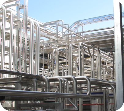
Automatic orbital gas tungsten arc welding is used in a variety of industries in which maximum leak integrity, high performance, or ultra-cleanliness is important. Automatic orbital welding provides enhanced precision and reliability compared to manual techniques. Small, portable inverter power supplies, advanced control systems, and other advancements have made orbital welding systems practical for a range of applications.
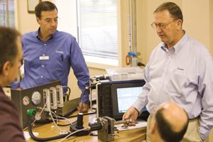
: Figure 1: Newer automatic orbital welding systems provide operators with many preset programs and enhanced user interfaces to assist with programming.
Many different industries use automatic orbital gas tungsten arc welding (GTAW) to help their products achieve maximum leak integrity, high performance, and ultracleanliness. The process is used in various applications, from the biopharmaceutical and semiconductor industries to petrochemical and power plants to chemical processing and refining operations.
Automatic orbital GTAW establishes an arc between a nonconsumable tungsten electrode (positioned in the weld head) and the base material that is being welded, creating a weld puddle. The electrode and weld puddle both are surrounded by a shielding gas, which is fed through the weld head to protect the electrode, molten weld puddle, and solidifying weld metal from atmospheric contamination. The heat produced by the arc melts the base material, and the electrode moves along the joint and progressively melts and joins the adjoining surfaces.
Small, portable inverter power supplies, advanced control systems, and other developments have made orbital GTAW systems practical for many applications. The advent of new technology has led to further improvements in the systems’ ease of use, weld consistency, and weld reliability.
Open Platform Design
Orbital welding power supplies have been incorporating more skills of the welder into the welding system itself, enabling efficiencies in automation, programming, and documentation. An open platform design allows an interface with standard devices and the ability to expand as technology evolves and needs change.
Programming. Every orbital weld, regardless of the application, requires the creation of a program that controls the output characteristics of the system. Systems can simplify programming by providing step-by-step procedures to create programs for many different tube diameters, wall thicknesses, and base materials (see Figure 1).
Rather than build programs manually using charts or tables, past weld parameter data, or memory, operators can create programs by selecting pertinent data from pick lists or drop-down menus. The system then creates the initial program for the operation, which reduces the chance for human error and decreases start-up time. This feature also is helpful for operators welding unfamiliar materials.
Newer orbital welding systems are available with integral USB ports that enable operators to plug in a keyboard, mouse, or number keypad for simplified data entry. Operators also can download welding programs via a USB flash drive or update operating system software to add features or functionality.
Documentation. In some industries, documentation of the weld is important for quality assurance and control. Traditionally, weld operators have had to maintain detailed, written weld logs that must be entered into databases and formatted into reports.
Today’s orbital welding technology enables this data to be stored within the system for retrieval and transfer to databases for analysis and reporting. Data management can help an organization track trends, review production rates, and calculate costs per weld.
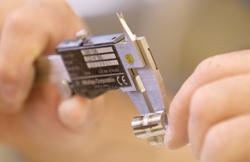
: Figure 2: Automatic orbital welding is a highly controlled process to ensure welds are consistent and repeatable.
High-speed thermal printers built into newer orbital welders also help with documentation. For example, users can print a hard copy reference of weld parameter details. Based on procedural requirements, operators might need to “coupon in” by creating a schedule, completing a weld, examining it for quality, and documenting these actions by printing the coupon. At specified intervals, the operator will perform similar actions to “coupon out.” Coupon printouts provide a record of verification to meet quality control requirements.
Weld Repeatability, Consistency, and Efficiency
With orbital welding, the electrode is rotated in an orbit around a joint on a rotor. The rotor and electrode are housed in the weld head, which rotates around the tube. The process is highly controlled to help ensure that high-quality welds can be produced on a consistent and repeatable basis (see Figure 2).
Variables are maintained at preset levels. The system automatically starts and completes the weld, stepping from one variable setting to the next at specific locations along the joint or at predetermined times during the process.
Gas Control. Newer orbital power supply designs feature automatic shield gas control to the weld head (see Figure 3). This helps eliminate operator inefficiency or the possibility of incorrect settings that could negatively affect weld quality. The controller adjusts gas flow automatically based on the program selected for a particular weld. The integrated flow controller also prevents operators from initiating the weld without gas flow, an error that could result in damage to the weld head or the workpiece.
Blast Purge. Further gas control advancements enable operators to improve their efficiency when welding at locations where the power supply is a long distance from the weld head. A sufficient gas volume must be present at the weld location before the weld starts. Blast purge fills gas lines rapidly, then automatically returns gas flow to normal levels, allowing operators to start a weld sooner.
Power Considerations
Power supplies with high power outputs can weld larger-diameter and heavy-walled tube and pipe while maintaining consistent welds. Newer welding systems offer the power output needed to weld the heavy-walled components found in general industrial applications like oil and gas, as well as smaller-diameter, thin-walled tubing for R&D or semiconductor applications.
Initializing the welding process requires a high-frequency, high-voltage arc start, which could result in electromagnetic interference (EMI). EMI is an electrical disturbance that can interfere with devices such as computers and other sensitive electronics. Excessive EMI in a welding project could cause computers to shut down and work to be lost. Welding systems with low-EMI arc start technology allow the arc start to occur without affecting the operation of equipment in proximity.
Portability and Accessibility
Small, lightweight orbital welding systems are designed for portability. Weld system power supplies can be moved easily from one job site to another. Remote controls and detachable weld heads and fixtures allow joints to be pre-positioned and enable welding in hard-to-reach places. There only needs to be enough clearance at the weld site to allow the weld head to make a full 360-degree orbit around the tubing.
As the world becomes a smaller place, a single welding system may be used across cultures and geographies. Welding systems with multiple language capabilities built into the interface let operators switch among languages at the touch of a button. Some welding systems also have universal voltage input that adjusts automatically to a country’s voltage input.
New advancements are helping orbital welding deliver repeatable, consistent, quality welds and making the process cost-effective and viable for plant managers and welding operators.
- Category: Uncategorised
Contractors Info
- Published: Monday, 07 November 2016 22:37
- Written by Super User
- Hits: 8052

We are a family company, which prides its self in the quality of work we produce for our clients. That’s why we try to work towards always finding a solution to any problem. Please feel free to speak to us regarding any issues and we will work with you to resolve them.
Site Rules
1. No unauthorised personal allowed on site
2. All workers must carry a white/yellow card
3. Foot protection and high vis worn at all times
4. All accidents or incidents must be reported
5. No smoking on site
6. You are required on site for the hours your supervisor stipulates
7. All overtime must be approved by a supervisor first
8. J&T shirts must be regularly washed and always worn on site
9. No soliciting work from clients within 6 months of your contract
10. Zero tolerances to drugs and alcohol
Fergus

At J&T we use an app called Fergus to track all project activities including your time. So instead of asking you to fill out a timesheet you can just download the app and record your time spent on each job.
Download it for free here:
Your supervisor will let you know which job numbers you will be working on when required.
Please note this to record your hours for the time you are asked to work, it’s not so you can invoice every minute you are over. We will not be docking you for every minute you are under. If your supervisor states you at working from 6am to 4:30pm, then these are the only hours you will record. Any overtime must be approved by your supervisor (see site rules).
LOG IN DETAILS
Log in - Your email address
Password – your mobile number
Once your logged in, click to the lower right on events to see the available job numbers
(As show below)
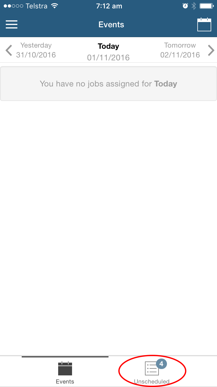
You can then start a timer or just add the time at the end
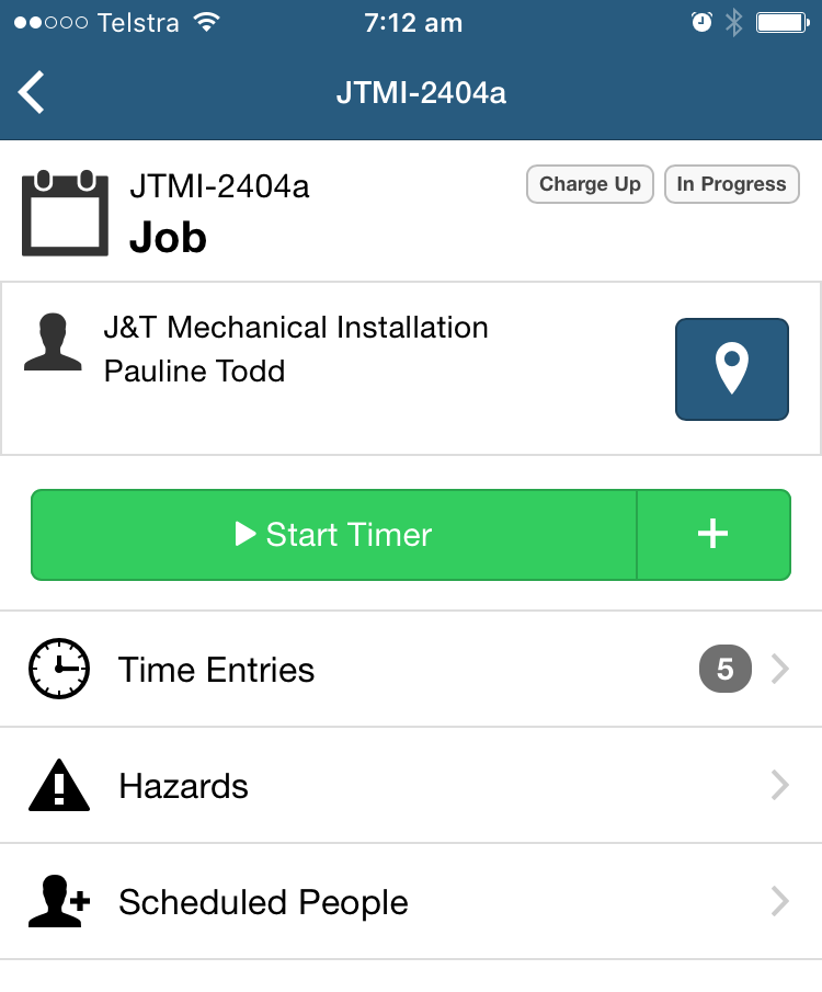
Once your time is complete you can add your unpaid break time.
Fergus will ask you to add a comment, please add what you worked on that day.
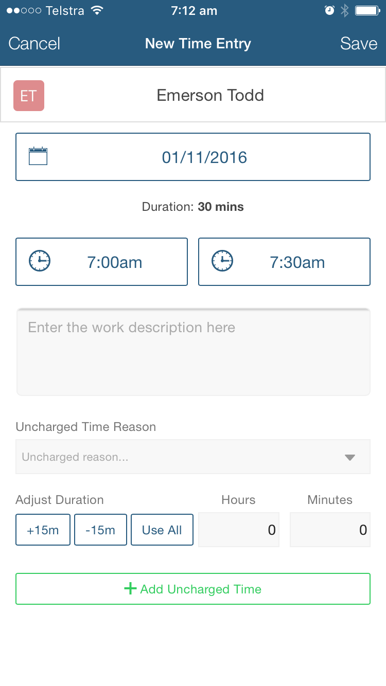
UNCHARGED TIME
You must add your uncharged break into fergus, using the the "UNCHARGED TIME REASON" drop down.
If you did not take a break, YOU MUST SAY SO IN YOUR COMMENTS.
Otherwise it will be assumed you forgot and it will be removed from your hours.
- Category: Uncategorised
Understanding the basic principles behind orbital tube welding
- Published: Monday, 13 July 2015 13:49
- Written by Super User
- Hits: 8705
Orbital Tube Welding
Understanding the basic principles behind orbital tube welding may help you arrive more rapidly at the optimum weld procedure for your specific application.
By Bernard Mannion and Jack Heinzman III
Orbital welding was first used in the 1960s, when the aerospace industry recognized the need for a superior joining technique for aerospace hydraulic lines. A mechanism was developed in which the arc from a Tungsten electrode was rotated around the tubing weld joint. The arc welding current was regulated with a control system thus automating the entire process. The result was a more precision and reliable method than the manual welding method it replaced.
In the early 1980s, Orbital welding became practical for many industries when combination power supply/control systems were developed that operated from 110 VAC. These systems were physically small enough to be carried from place-to-place on a construction site for multiple in-place welds. Modern day orbital welding systems offer computer control, where welding parameters for a variety of applications can be stored in memory and later called up for a specific application. Hence, the skills of a certified welder are thus built into the welding system, producing enormous numbers of identical welds and leaving significantly less room for defects.
Orbital Welding Equipment
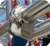
In the orbital welding process, tubes/pipes are clamped in place, and an orbital weldhead rotates an electrode and electric arc around the weld joint to make the required weld. An orbital welding system consists of a power supply and an orbital weldhead.
The power supply/control system supplies and controls the welding parameters according to the specific weld program created or recalled from memory This supply provides the control parameters, the arc welding current, the power to drive the motor in the weldhead, and switches the shield gas(es) on/off as necessary.
Orbital weld heads are normally of the enclosed type, and provide an inert atmosphere chamber that surrounds the weld joint. Standard enclosed orbital weld heads are practical in welding tube sizes from 1/16 inch (1.6 mm) to 6 inches (152 mm) with wall thicknesses of up to .154 inches (3.9 mm). Larger diameters and wall thicknesses can be accommodated with open style weld heads.
Reasons for Using Orbital Welding Equipment
Sidebar - Can it save you money?
There are many reasons for using orbital welding equipment. The ability to make high quality, consistent welds repeatedly, at a speed close to the maximum weld speed, offer many benefits to the user:
- Productivity. An orbital welding system will drastically outperform manual welders, many times paying for the cost of the orbital equipment in a single job.
- Quality. The quality of a weld created by an orbital welding system (with the correct weld program) will be superior to that of manual welding. In applications such as semiconductor or pharmaceutical tube welding, orbital welding is the only means to reach the weld quality requirements.
- Consistency. Once a weld program has been established, an orbital welding system can repeatedly perform the same weld hundreds of times, eliminating the normal variability, inconsistencies, errors, and defects of manual welding.
- Skill level. Certified welders are increasingly hard to find. With orbital welding equipment, you don't need a certified welding operator. All it takes is a skilled mechanic with some weld training.
- Versatility. Orbital welding may be used in applications where a tube or pipe to be welded cannot be rotated or where rotation of the part is not practical. In addition, orbital welding may be used in applications where access space restrictions limit the physical size of the welding device. Weld heads may be used in rows of boiler tubing, where it would be difficult for a manual welder to use a welding torch or view the weld joint.
Many other reasons exist for the use of orbital equipment over manual welding. For example, applications where inspection of the internal weld is not practical for each weld created. By making a sample weld coupon that passes certification, the logic holds that if the sample weld is acceptable, that successive welds created by an automatic machine with the same input parameters should also be sound.
 |
| Standard enclosed orbital weld heads are practical in welding tube sizes from 1/16 inch (1.6 mm) to 6 inches (152 mm) with wall thicknesses of up to .154 inches (3.9 mm) Larger diameters and wall thicknesses can be accommodated with open style weld heads. |
General Guidelines for Orbital Tube Welding
For orbital welding in many precision or high purity applications, the base material to be welded; the tube diameter(s); weld joint and part fit-up requirements; shield gas type and purity; arc length; and Tungsten electrode material, tip geometry, and surface condition may already be written into a specification covering the application.
Each orbital welding equipment supplier differs slightly in recommended welding practices and procedures. Where possible, follow the recommendations of your orbital equipment supplier for equipment set-up and use, especially in areas that pertain to warranty issues. Note that, this section is only intended as a guideline for those applications where no specification exists. The engineer responsible for the welding must create the welding set-up, and derive the welding parameters, in order to arrive at the optimum welding solution.
Welding Basics and Set-Up
The Physics of the GTAW Process
The orbital welding process uses the Gas Tungsten Arc Welding process (GTAW), as the source of the electric arc that melts the base material and forms the weld. In the GTAW process (also referred to as the Tungsten Inert Gas process -- TIG) an electric arc is established between a Tungsten electrode and the part to be welded. To start the arc, an RF or high voltage signal (usually 3.5 to 7 KV) is used to break down (ionize) the insulating properties of the shield gas and make it electrically conductive in order to pass through a tiny amount of current. A capacitor dumps current into this electrical path, which reduces the arc voltage to a level where the power supply can then supply current for the arc. The power supply responds to the demand and provides weld current to keep the arc established. The metal to be welded is melted by the intense heat of the arc and fuses together.
Material Weldability
The material selected varies according to the application and environment the tubing must survive. The mechanical, thermal, stability, and corrosion resistance requirements of the application will dictate the material chosen. For complex applications, a significant amount of testing will be necessary to ensure the long term suitability of the chosen material from a functionality and cost viewpoint.
In general, the most commonly used 300 series stainless steels have a high degree of weldability with the exception of 303/303SE which contain additives for ease of machining. For hundred series stainless steels are often weldable, but may require post weld heat treatment.
Accommodation must be made for the potential differences of different material heats. The chemical composition of each heat batch number will have minor differences in the concentration of alloying and trace elements. These trace elements can vary the conductivity and melting characteristics slightly for each heat. when a change in heat number is make, a test coupon should be make for the new heat. Minor changes in amperage may be required to return the weld to its original profile.
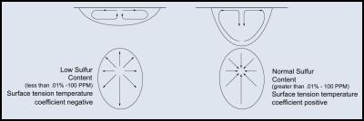
It is important that certain elements of the material be held to close tolerances. Minor deviations in elements, such as sulfur, can vary the fluid flow in the weld pool, completely changing the weld profile and causing arc wander.
 |
| For orbital welding, the goal is to have the minimum sufficient weld penetration to consistently weld through the tube wall. |
 |
| How electrode tip geometry affects the weld profile. |
Weld Joint Fit-Up
Weld joint fit-up is dependent on the weld specification requirements on tube straightness, weld concavity, reinforcement, and drop through. If no specification exists, the laws of physics will require that the molten material flow and compensate for tube mismatch and any gap in the weld joint.
Tubing is produced according to tolerances that are rigid or loose according to the application for which the tube was purchased. It is important that the wall thickness is repeatable at the weld joint from pat to part. Differences in tube diameter or out-of-roundness will cause weld joint mismatch and arc gap variations from one welding set up to another.
Tube and pipe end prep facing equipment is recommended in order to help ensure end squareness and end flatness. Both the O.D. and O.D. should be burr free with no chamfer.
When two tubes are butted together for welding, two of the main considerations are mismatch and gaps. In general, the following rules apply:
- Any gap should be less than five percent of the wall thickness. It is possible to weld with gaps of up to 1- percent ( or greater) of wall thickness, but the resultant quality of weld will suffer greatly, and repeatability will also become a significant challenge.
- Wall thickness variations at the weld zone should be +/- five percent of nominal wall thickness. Again, the laws of physics will allow welding with mismatch of up to 25 percent of wall thickness if this is the only challenge. Again, the resultant quality of weld will suffer greatly, and repeatability will become an issue.
- Alignment mismatch (high-low) should be avoided by using engineering stands and clamps to align the two tubes to be welded. This system also removes the mechanical requirements of aligning the tubes from the orbital weldhead.
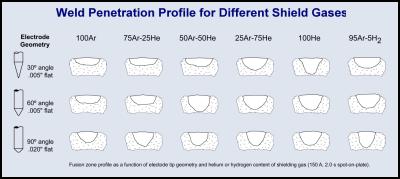 |
| Minor changes in sulfur content can change weld pool flow characteristics with a dramatic effect on penetration (The Maragoni Effect). |
Shield Gas(es)
An inert gas is required on the tube O.D. and I.D. during welding to prevent the molten material from combining with the oxygen in the ambient atmosphere. The objective of the welder should be to create a weld that has zero tint at the weld zone I.D.
Argon is the most commonly used shield gas (for the O.D. of the tube and the purge gas (for the I.D. of the tube). Helium is often used for welding on copper material. Mixed gases, such as 98 percent Argon/two percent Hydrogen; 95 percent Argon/five percent Hydrogen; 90 percent Argon/10 percent Hydrogen; or 75 percent Helium/25 percent Argon may be used when the wall thickness to be welded is heavy (.1" or above). Using mixtures of 95 percent Argon/five percent Hydrogen is incompatible with carbon steels and some exotic alloys, often causing hydrogen embrittlement in the resultant weld. As a general rule, for simplicity and reduction of shield gas cost, use 100 percent Argon gas.
Gas purity is dictated by the application. For high purity situations, where the concern for micro-contamination is paramount, such as semiconduction and pharmaceutical applications, the shield and purge gases must minimize the heat tint that could otherwise be undesirable. In these applications, ultra high purity gas or gas with a local purifier are employed. For non-critical applications, commercial grade argon gas may be used.
 |
| The combination of the electrode tip geometry and shield gas can have a major effect on the weld penetration, weld quality, welding speed, and electrode life. |
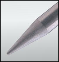 |
| Using pre-ground electrodes ensures that the electrode material quality, tip geometry, and ground electrode surface input to the welding process is constant. |
Tungsten Electrode
The Tungsten welding electrode, the source of the welding arc, is one of the most important elements of the welding system that is commonly ignored by welding system users. Users continue to manually grind and wonder why they produce inconsistent results. Whether in manual or automatic welding, this is the area where manufacturing organizations can improve the consistency of their welding output with minor effort.
Basically, the objective for the choice of Tungsten parameters is to balance the benefits of a clean arc start and reduced arc wander with good weld penetration and satisfactory electrode life.
Electrode Materials
For quite some time, Tungsten manufacturers have added an oxide to pure Tungsten to improve the arc starting characteristics and longevity of pure Tungsten electrodes. In the orbital welding industry, the most commonly used electrode materials are two percent thoriated Tungsten and two percent ceriated Tungsten.
| Many users of the TIG welding process do not realize that the welding electrode they use contains Thorium, a radioactive element added to the Tungsten. |
Safety
The safety issues of Tungsten electrode material are now being looked at more closely. Many users of the TIG welding process do not realize that the welding electrode the use contains Thorium, a radioactive element added to the Tungsten. While the radioactivity is of a low level, it brings an issue of danger, especially with the radioactive dust that is generated when grinding the electrodes to a point for welding.
Alternative, non-radioactive Tungsten materials are now available, such as two percent ceriated electrodes, which often offer superior arc welding. While these materials are commercially available they have been largely ignored until recently.
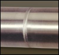 |
| A typical orbital tube weld. Note the pulsed arc finish on the weld surface. |
Recommended Electrode Materials
Cerium, as a base material, has a lower work function than Thorium, offering superior emission characteristics. So, not only do ceriated electrodes offer an advance in electrode safety, they also improve the arc starting ability of the orbital equipment. However, as mentioned earlier, it is always best to follow the advice of your orbital equipment manufacturer.
Electrode Tip Geometry
Given the ever-increasing weld quality requirements of the final weld, more and more companies are looking for ways to ensure that their weld quality is up to par. Consistency and repeatability are key to welding applications. The shape and quality of the Tungsten electrode tip is also being recognized as a vital process variable. Once a weld procedure has been established, it is important that consistent electrode material, tip geometry, and surface condition be used.
Welders should follow an equipment supplier's suggested procedures and dimensions first, because they have usually performed a significant amount of qualifying and troubleshooting work to optimize electrode preparation for their equipment. However, where these specifications do not exist, or the welder or engineer would like to change those settings to possibly improve and optimize their welding, the following guidelines apply:
Electrode Taper
This is usually called out in degrees of included angle usually anywhere between 14deg and 60deg). Below is a summary chart that illustrates how different tapers offer different arc shapes and features:
| Sharper Electrodes | Blunter Electrodes |
| Last less than blunt | Last longer |
| Less weld penetration | Better weld penetration |
| Wider arc shape | Narrower arc shape |
| Handle less amperage | Handle more amperage |
| Less arc wander | Potential for more arc wander |
| More consistent arc | Less consistent arc |
To demonstrate graphically how the taper selection will effect the size of the weld bead and the amount of penetration, the drawing on page 20 show typical representations of the arc shape and resultant weld profile for different tapers.
Electrode Tip Diameter
Grinding an electrode to a point is sometimes desirable for certain applications, especially where arc starting is difficult or short duration welds on small parts are performed. In most cases, however, it is best for a welder to leave a flat spot or tip diameter at the end of the electrode. This reduces erosion at the thin part of a point, and reduces the concern that the tip may fall into the weld. Larger and smaller tip diameters offer the following trade-offs:
| Smaller Tip | Larger Tip |
| Easier to start | Usually harder to start |
| Less arc wander | More chance of arc wander |
| Less electrode life | More electrode life |
| Less weld penetration | More weld penetration |
Tungsten Electrode Grinder and Pre-Ground Electrode
Using electrodes pre-ground to requirements or a dedicated commercial electrode grinder to provide electrode tip quality and consistency, offers the following benefits to the user in their welding process:
- Improved arc starting, increased arc stability, and more consistent weld penetration.
- Longer electrode life before electrode wear or contamination.
- Reduction of Tungsten shedding. This minimizes the possibility of Tungsten inclusions in the weld.
- A dedicated electrode grinder helps ensure that the welding electrodes will not become contaminated by residue or material left on a standard shop grinder wheel.
- Tungsten electrode grinding equipment requires less skill to ensure that the Tungsten electrode is ground correctly and with more consistency.
Pre-Ground Electrodes
Rather than risk electrode radioactivity issues, and constantly endure the variability of each operator grinding the electrodes with a slightly different touch, many manufacturing organizations have chosen to purchase electrodes pre-ground. Since a small difference in the dimensions of an orbital electrode can produce a big difference in the weld results, pre-ground electrodes are the preferred electrode choice to maintain the consistency of your welding. This low-cost option ensures that the electrode material quality, tip geometry, and ground electrode surface input to the welding process is constant. Consult electrode charts or a pre-ground electrode supplier to obtain the electrode diameter and tip geometry that is most suitable for your welding application.
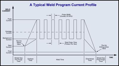 |
| This weld profile shows a single level of weld time. Orbital welding normally uses a minimum of four levels of weld time, with each level decreasing in weld amperage as the tube heats up during the welding process. |
image - weld profile
Conclusion
In conclusion, the important points to remember are:
- Orbital welding has been used by many industries to improve the quality and quantity of tube welding when compared to what can be accomplished by manual welders.
- The effective cost of an employee computes to be significantly more that just his base salary. The output of a $20 per hour skilled welder actually costs over $72,000 per year (almost twice his yearly base wage).
- If a complete orbital welding system costs between $15,000 and $20,000 and can output over twice the amount of welding that a manual welder can produce when the equipment will pay for itself in a matter of months.
- Finally, the volume of welds that are produced by an automated welding system will far exceed that of a manual welder. In addition to weld quality improvements, this will bring two additional financial benefits: One, increased output per day at lower cost. Two, lowered scrap and rework costs due to improved weld consistency.
|
||||||||||||||||||||||||||||||||||||||||||||||||||||||||||||||||||||||||||||||||||||||||||||||||||||
Ref - http://www.pro-fusiononline.com/feedback/fc-dec99.htm
- Category: Uncategorised


